All Diagrams
This section gives the general requirements; requirements for specific types of diagrams are below.
- Use CamelCase for class names, meaning use upper-case letters for the first word and all following words, lower case for all other letters. The exceptions would be class names in some libraries (for example, the C++ STL) and standard abbreviations (such as MSOE).
- Avoid non-standard abbreviations. “App” is fine, but most other abbreviations are not. They make code hard to maintain because other developers have to remember which abbreviations you prefer. For the same reason, avoid spelling errors, especially for words within names.
- All classes should be associated with at least one other class.
- Avoid redundancy. For example, if class A relates to B and B relates to C, there is rarely any need for A to relate directly to C. As another example, avoid showing a relationship to another class and listing an instance of that class in the box. The relationship implies the instance.
- Avoid the aggregation symbol (open diamond) on associations. Many people believe there is a strong distinction between this and other associations, but in fact the UML standard gives no meaning to this notation.
- Avoid the uses symbol (dashed arrow) on associations. These are temporary associations related to a particular implementation of a method, and of limited value to understanding the structure of a system. They often capture a particular implementation, nothing They make a diagram hard to read without adding value.
In general, be careful on how you use UML notation. UML is very carefully designed to convey key information without unnecessary redundancy. Non-standard notation adds confusion, defeating the purposes of drawing diagrams in the first place. This is especially important in the core notation: using open triangles for generalization, open (v-shaped) arrows for direct association, solid lines for associations, etc. Learning to use the correct notation can be very important for interviews because it’s one way people sort out those who have learned basic software engineering concepts from those who have not.
Domain Level Class Diagrams
In addition to the requirements for all diagrams, domain-level class diagrams must meet the following requirements. See this page for an example domain level diagram along with an implementation.
Show inheritance, attributes, methods, relationships, and multiplicities.
- Generally, multiplicities will be either
1or*, and1is assumed if there is no indication. However, if a problem statement explicitly gives numbers, use those numbers (like3..6if there is a requirement for three to six items of something). - Use
0..1for an optional item,1..*for one or more. - Never write
0..*; this is always written as simply*.
Show role names when they add information, such as when there are two distinct associations between the same classes. For example:
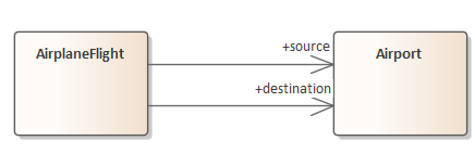
If “has-a” is a reasonable read of the domain, add the arrow at the end of the association to capture this relationship. But it is also always appropriate to just use undirected associations since directionality is often a performance issue.
If the domain makes it clear that a class “needs” another, use the composition relationship (filled-in diamond) with an arrow. This can capture something like “a plane needs wings”. But it is also acceptable to use just a standard line (one class is associated with another) in such cases. Never use the open diamond; this notation has no real meaning.
List just simple attributes inside the class box. Complex attributes – that is, ones that are instances of other domain classes – need to be shown by explicit associations instead. That is, do not list an attribute in a class box when it would be redundant with an association.
Domain-level designs need to be independent of a programming language; do not include Java-specific classes.
- This means you would not use Java-specific classes like
LinkedListorMap. Just use a one-to-many relationship between an object (like a Bus) and the objects it contains (like Passengers). - Also, do not include a class that simply contains a
static main; this is also a Java-specific concept.
It is not required to mark classes as abstract or interfaces. It is allowed, but this is often an implementation issue and preferably does not appear in a domain diagram.
Do not specify types, constructors, getters, or setters; they add clutter and obscure the important concepts for clients.
Very high level domain diagrams may even omit attributes and operations; ask if you are not sure if they should be included.
Minimal Solution Diagram
This is called an abstract solution diagram in some contexts.
In addition to the requirements for all diagrams, minimal solution diagrams capture the domain and the design decisions. They exist in the solution space: that is, they capture details that are not typically visible to clients such as containers and design patterns. In particular, a minimal solution diagram includes the following:
- Domain classes which appear in the solution. If a domain class has no responsibilities that are relevant to the rest of the application, then it may not be needed. Be careful about removing domain classes; lack of responsibilities may indicate missing requirements!
- Inheritance (including realization), attributes, methods, relationships, and multiplicities. The distinction between interfaces and abstract classes is important in these diagrams.
- Attribute and method types where known and relevant to understanding the design, but not all types. Types for simple attributes are often very useful, but types for methods are often too detailed for this diagram.
- Constructors, getters, and setters should generally be omitted unless they are important to understanding the design.
- As for other diagrams, do not list an attribute in a class if there is an association for that attribute to another class. List just simple attributes inside the class’s box.
- Show role names when they add information (as discussed above).
- When known, Container classes like
Hashtablethat appear in the solution. For example, if your solution will contain a map from student id numbers (integers) to student objects, include a classMap<int, Student>in your diagram and add a one-to-many association from this class to classStudent. You likely do not need to document the attributes and methods in these classes since they are just those in the standard Java library. It is acceptable to not specify the container if that design decision has not been made at the time the diagram is being created. - Design patterns applied to the solution. That is, those classes that implement design patterns that appear in the solution.
Note that setters, getters, and constructors are not included. Neither are
JavaFX classes or a class for main. See the Ice Cream Cone Decorator
example for a sample minimal solution diagram.
Contract Diagrams
“Contract” diagrams give full details needed by other developers, including type information. These must also follow the general requirements for all diagrams.
- Show inheritance, attributes, methods, relationships, and multiplicities.
- Make all associations directed. If an association is bi-directional (two classes both have a reference of the other), show that as two separate, directed associations.
- Missing multiplicities are assumed to have the value 1.
- Use a filled-in diamond on an association when it’s directed and the source “needs” the destination class. Do not use the empty diamond (aggregation) since it has no true meaning in the standard.
- Mark abstract classes using the notation of your target language. For example, Java developers will distinguish between abstract classes and interfaces.
- Unless directed otherwise, include all setters, getters, constructors.
- Unless directed otherwise, include all type information, both for attributes and for parameters.
- Show role names when they add information (as discussed above).
This diagram differs from reverse-engineered diagrams in that it omits a number of superfluous elements such as named constants and duplicating associations as attributes.
Reverse-Engineered Diagrams
Use Enterprise Architect (EA) to generate a reverse-engineered diagram. See this page for directions. After reverse engineering a class diagram in EA, the only change you need to make is to reorganize the classes to minimize the number of crossing lines and the amount of white space. The diagram is to fit on a single page if at all possible. These diagrams will not satisfy the above requirement for avoiding redundant attributes, but you are not expected to fix this problem.